


What are the latest specialized rigging projects across North America?
25 October 2023
Rigging challenges are nothing new to the specialized lifting and rigging industry. The companies thrive on projects that seem impossible. They often require high level engineering expertise, and even reverse engineering.
 Barnhart’s Mandan, ND branch, which was hired to provide engineering, crane and transport solutions for the project, that was part of a casino and lodge, in New Town, ND.
Finding the right and safe process and equipment to lift, move and install equipment in challenging environments offers a sense of satisfaction that keeps these teams looking for the next rigging problem to solve.
ACT rounded up eight rigging jobs around the country that represent innovation at its highest level.
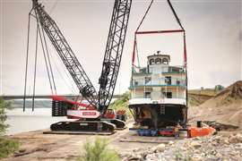
Riverboat launch
Launching a riverboat was a thought-provoking process for Barnhart’s Mandan, ND branch, which was hired to provide engineering, crane and transport solutions for the project, that was part of a casino and lodge, in New Town, ND.
The 80-foot boat riverboat was delivered to New Town in eight pieces. It was fully constructed on site about a quarter mile from the lake. This was her first launch.
 Barnhart used hydraulically adjusted tension links in the rigging to be able to level the boat in the event the actual center of gravity was offset from the theoretical location.
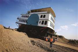
Beyond the many rigging challenges to master, the boat and crane had to be transported down a 16.8 percent grade to reach the launch at Lake Sakakawea. Plus, the boat’s interior was not fully outfitted when the project took place.
The center of gravity (CG) had been estimated, but Barnhart decided to include hydraulically adjustable tension links in the rigging to have the ability to level the boat in case the actual CG was offset from the theoretical location.
The shell plate of the hull was only a quarter-inch thick. To avoid damaging the thin plate, the transverse slings under the hull had to be positioned at predetermined locations at internal frames and bulkheads. In addition, the profile of the hull changed along the length of the boat.
 Precise engineering was required to determine where the slings should be positioned.
This required a significant amount of engineering to calculate precise rigging lengths for the support points. Adjustable rigging and multiple spreader bars were engineered to accommodate this lift.
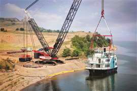
Barnhart utilized their Terex CC 2800-1 SSL, 300Kip and 120Kip Tension links. The riverboat was transported several hundred yards down the steep incline on a double wide 12-line Goldhofer PST. The crane with counterweight was walked down the same incline to the second crane pad.
The riverboat was lifted off the Goldhofer and successfully set in Lake Sakakawea.
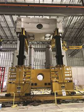
Pressed for space
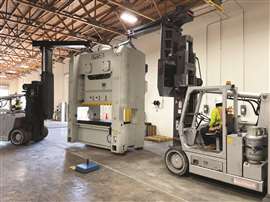 Two 40/60 Versa-Lifts were used to unload the press and stage it inside the building.
MEI Rigging & Crating was approached by a manufacturing company that was assessing the feasibility of installing a 60,000-pound press. The primary concern was the height inside the building, as they preferred not to cut a hole in the roof. After evaluating the requirements, MEI proposed an innovative alternative solution using Versa-Lift forklifts.
To execute the installation, the MEI team utilized two 40/60 Versa-Lifts to unload the press from the truck and stage it inside the building. Once the press was on the ground, the rigging crew utilized boom attachments and rigged the top of the press in preparation for lifting. Ensuring stability, the crew had another forklift positioned at the bottom of the press. With the necessary precautions in place, the MEI crew began the lifting process, raising the press straight up and eventually standing it upright.
After achieving the desired position, the crew carefully maneuvered the press into place as directed by the manufacturing company.
MEI Rigging & Crating constantly seeks to provide new and innovative solutions to their customer’s problems and needs to earn and keep their business, the company said.
Railroad bridge switchout
L.G. Barcus & Sons was tasked with replacing an old railroad bridge with a new 135-foot, 536-ton steel span within just 22 hours. Traditional lift plans were deemed unsuitable due to weight and headroom issues.
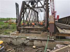 By adding additional skid shoes, the Hydra-Slide’s 500-ton capacity was increased to 750 tons.
The plan was altered to utilize a Hydra-Slide Skidding System, provided by LGH. By adding additional skid shoes, the Hydra-Slide’s 500-ton capacity was increased to 750 tons.
The team built the new bridge atop Hydra-Slide track sections, employing special steel frames around each bearing pad. Additional support was created with h-piles, steel caps and temporary footings. The old bridge was cleared, making way for the new structure.
Two synchronized Hydra-Pac systems powered the sliding process. Within around 30 minutes, the bridge was correctly positioned. Hydraulic jacks lifted the bridge off the Hydra-Slide. The team then removed the tracks and lowered the bridge into place. The final step included installing two 50-foot steel spans on either side of the new bridge.
The success of the LGH and Hydra-Slide collaboration allowed L.G. Barcus & Sons to meet the customer’s tight deadline without any issues.
Superintendent Marshall Chambers praised the Hydra-Slide’s effectiveness, noting that it was easier to use than traditional cranes.
“This project’s success showcases LGH’s ability to help you tackle complex rigging challenges in any industry,” stated the LGH team.
Shallow pit challenge
DHGC was contracted through Schuler to install a five-stand press line. The presses were 1,200 to 2,500 metric tons.
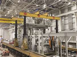 DHGC installed a five-stand press line in a shallow 5-meter-deep pit.
The pit was only 5 meters deep instead of the standard 6 meters. As a result, to clear the tie rods DHGC had to put its gantry on 6-foot stands and use 30-inches for a total height of 9 feet.
Crown shipments were delayed 5 weeks forcing DHGC to prebuild all but four presses. A result they had to travel 160 feet with 430,000 pounds at a height over 40 feet. The team managed to reduce the 5-week lost time down to 3 weeks.
Equipment used included RGS 5400 towers, 50 and 30-foot box beams, 250-ton side shifts, Hoist 40/60, Hoist 25/35 and a 4-lLine SPMT.
Switching gears
A major utility provider contacted Edwards Moving & Rigging to devise a plan to place seven Switch Gear packages into a second-floor building at a site near Cincinnati, OH. Even though the Switch Gear components were relatively light, ranging from 6,000 to 20,500 pounds, the challenge of getting them from a flatbed to the point of final placement in a very restricted location required a detailed, creative and innovative plan by the Edwards engineering team.
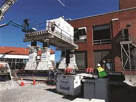 Project obstacles included overhead lines above the opening into the building, restricted space in the switch gear yard, a tight and off-center opening, low ground pressure and equipment inside the building had to be moved around by hand.
The obstacles to overcome on this project included overhead lines directly above the opening into the building, restricted space in the switch gear yard, a tight second floor opening that was off center, low allowable ground pressure on the second floor, and all equipment inside the building had to be moved around by hand.
The accessibility limitations required an agreement with an adjacent property owner to allow a crane on their property from which all rigging gear and the Switch Gear units would be offloaded from a flatbed and placed onto utility property.
The crane first set up Edwards’ 500-ton capacity gantry, which would serve as the base for a moving platform. The gantry legs were placed on a track positioned over load spreading mats. This design facilitated movement from the fence on the boundary nearest the crane to the second-floor opening.
 The final portion of the scope was to move all Switch Gear to the center of the building, and set them into final position.
Edwards built a special sliding frame on which to place the Switch Gear. The frame allowed the components with an open bottom to be slid as needed, and since there were no jack lugs on the Switch Gear, the frame was used for jacking operations as required to remove the slide system and reinstall it for the next unit. As the trucks brought the Switch Gear onto the adjacent property, the crane picked them and placed them on the work platform.
Edwards then trolleyed the load to the side opening in the second floor. To transition the Switch Gear into the building, Edwards used a combination of aluminum beams and Hydra-slide Extreme Low-Profile Slide to move them from the platform through the second-floor opening.
The inside of the structure was carefully marked to ensure any jacking took place over a floor joist or beams that bridged multiple joists. The team transitioned from heavier beams on the platform to lighter beams inside. No material handling equipment was accessible on the second floor due to the ground bearing issue, making lighter equipment essential to the operation. All seven Switch Gear units were staged in alignment on temporary material.
The final portion of the scope was to move all Switch Gear to the center of the building, and set them into final position, with all staging material removed. The Edwards engineering team designed a system utilizing an internally fabricated gantry, featuring hollows jacks. The gantry was skated into position, each Switch Gear component in turn was slid under the gantry via the low-profile slide.
Once in position, the hollow jacks were positioned directly over the lift points on the Switch Gear. The Switch Gear was elevated, the dunnage removed and final set was completed. The Edwards team completed the project without incident and with an undamaged floor due to strict adherence to a comprehensive and carefully crafted engineering procedure.
Saddling up a slug catcher
Buckingham Heavy Transport was contracted to assist with the delivery of a 450,000-pound slug catcher from a bulkhead on the Ohio River to its destination site 50 miles west of the river in Ohio.
The Buckingham team pulled permits for a gross weight of 756,000 pounds and configured a transport plan which incorporated custom steel saddles, a Goldhofer PST/E trailer, a 500-ton gantry and two trucks and 12 axles of Goldhofer dual-lane trailer to handle the various challenges of the delivery route.
The slug catcher was transported via barge for the first stage of the journey. Buckingham designed and fabricated steel saddles and shipped them to the heavy haul company that was handling the transport to the barge in Texas. The saddles allowed the cylindrical slug catcher to be safely positioned on its side for transport, which would reduce load height and eliminate extra permitting and line fees for the overland sections of the route. When the barge arrived at the bulkhead, the barge crew offloaded the slug catcher by crane to Buckingham’s Goldhofer PST/E trailer, which could navigate the steep grade and sharp turn required to exit the bulkhead. In a gravel staging area at the top of the grade, Buckingham used a 500-ton gantry system to transload the 66 by 13 by 14-foot slug catcher from the Goldhofer PST/E trailer to the 12 axles of Goldhofer dual-lane trailer which they would use for the main portion of the transport.
The overland transport route was hilly with narrow roads and multiple tight turns. Buckingham’s vehicle tracking and swept path analysis enabled the team to choose the most efficient route for the delivery and to preemptively identify and mitigate problematic sections of the 50-mile route. The combined 1210 horsepower in the two Kenworth W-990 trucks were put to good use, pushing and pulling the 110-foot long, 16-foot-wide trailer up the hills heading northwest towards the destination. The transport was completed without events, and at the site, crane operators offloaded the slug catcher to its final location.
Container cranes takedown
When three ship-to-shore container cranes at a Virginia port were due for demolition, an innovative solution was needed to ensure a controlled dismantling. Engineered Rigging (ER) worked with RLT Engineering to determine that an 800-metric ton strand jack system was the best solution.
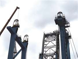 Engineered Rigging worked with RLT Engineering to determine that a strand jack system was the best solution for dismantling three container cranes at a port in Virgina.
A set of four 200-ton strand jacks, four hydraulic pumps, load anchors, wedges, strand and mounting grillage from ER’s rental fleet would provide the lifting capacity to safely hold the main boom and trolley beam of the crane in place while it was cut free from the portal gantry legs. That entire section (inclusive of the main front boom, mast, backstay bracing, machinery house, trolley beams, hoist, trolley, spreader and operator cabin) weighed about 600 tons.
To ensure proper load distribution, ER’s certified equipment technicians engaged and checked the system load readings and then initiated adequate lifting pressure on the reinforced shoulder girders. Before the cutting process began, the team went over pre-project checks, held safety meetings and planned for the controlled lowering sequence from the 150-foot elevation to the bottom seaside and landside cross beams for further dismantling.
Once the upper cross beams were free and clear, the technicians lowered the boom and trolley assembly until it was secure on the bottom landside and seaside cross beams. The loads for each jack were monitored throughout the synchronized lowering process by the SCC computer system. The boom segments were then secured to the bottom landside and seaside crossbeams so that the dismantling operations could begin.
The original strand jack system was then disassembled and reassembled for the next portal crane. The cutting and controlled lowering process was repeated until the booms from all three cranes were safely lowered and secure.
Mission impossible, almost
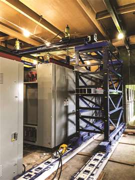
 The tie rods were set with a 75-ton Mobilift and Hoist 40/60, with inches to spare.
GICC was called in to take over a project that another rigging contractor could not perform. This was understandable because of interferences within a work area of 50-foot square area. As well, the scrape tunnel that ran through the area had no weight capacity, and the overhead cranes limited the height to just 33 feet. The pit was only 4 meters deep with no tie rod pockets.
GICC moved all equipment into place using its 4-line SPMT. The tie rods were set with a 75-ton Mobilift and a Hoist 40/60, with inches to spare.
Due to the overhead crane interference and the shallow pit depth, the team had to under pick the crown to set over tie rods.
“To maintain the schedule, we brought in two 140-ton capacity cranes to set the oil platform,” the company said. “Once we figured out all the quirks, we set a press in six days.”
Equipment used included two RGS 5400 towers, a 50-foot box beam, 250-ton side shifts, Hoist 40/60 lift truck, RGS 75-ton Mobilift and four lines of SPMT.
STAY CONNECTED

Receive the information you need when you need it through our world-leading magazines, newsletters and daily briefings.