


How to calculate the necessary support under a crane
24 May 2021
Technical: Ground pressure. Sure-footed
Stay on the side of caution when calculating the necessary support under a crane to ensure all cases of load and pressure can be handled. Keith Anderson explains
When lifting with a mobile crane, it is vital it is to provide a level load-sustaining base to support the crane and avoid it tipping in use. Generally, this is well understood and is taken seriously. However, cranes can also impose high loads and pressures in other circumstances such as when raising a boom and jib or, in the case of a crawler crane, when relocating unloaded. This is less well understood or accounted for and has high potential for creating problems.
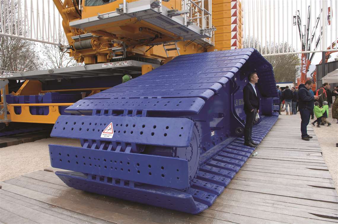 Whether lifting or relocating a crane be sure to consider and cater accordingly
First, some fundamentals. Achieving good support may involve some ground preparation and-or improvement and likely some matting to distribute the imposed loads to a level that the ground can safely withstand without failure or excessive settlement.
So, when designing a support system, there are first some logical steps to be taken and questions to be asked:
i. what is the maximum load or pressure the crane will impose in use?
ii. what can the ground safely withstand?
iii. how effective is the matting or other distribution system in distributing the loads?
To address these questions, there are tools available. Many crane manufacturers (and others) offer ground bearing pressure estimators or software (stand-alone or in-built) that allow the lift planner to estimate the loads and pressures the crane will impose; regarding ground capability, there are a number of avenues to determining a design pressure, including soil testing, boring logs, historical information, codes and presumptive figures; for matting analysis there is advice to be found in text books and publications, if all else fails, there are conservative rules of thumb (not recommended).
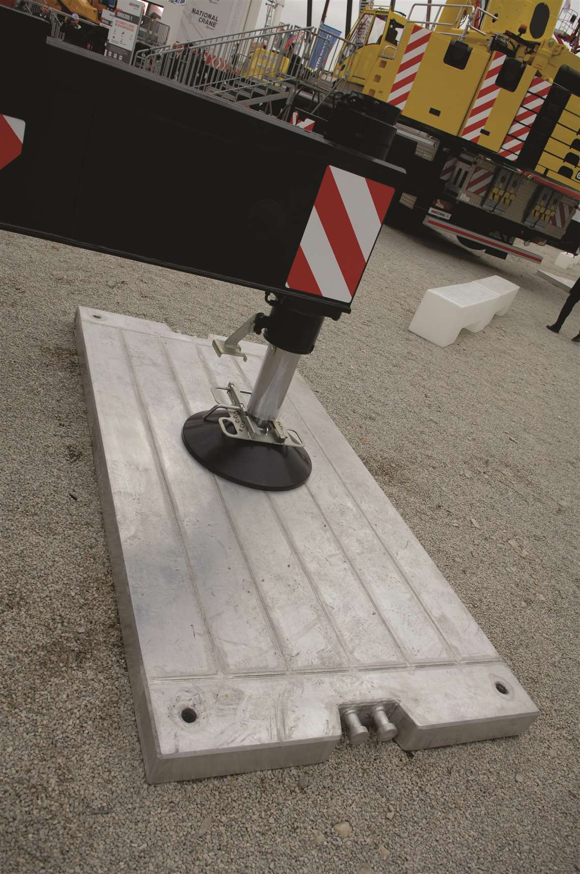 Proper support is vital and often easy enough to use
There are relatively few instances of cranes overturning during lifting when these questions are correctly addressed. In the real world, however, when dealing with non-engineered more “routine” operations and less certain ground conditions without a defined bearing figure and no geotechnical support, it might be appropriate to simply take a very conservative approach to load distribution to cover the uncertainty.
So, if we are doing our job right, when planning and executing a lifting operation, we should be giving some concentrated attention to ensuring the crane is well supported. This is all well and good when actually lifting but what about the loads and pressures that are imposed when raising a long boom or relocating a crawler crane?
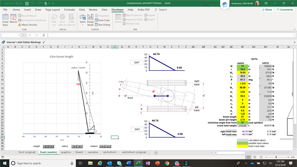
To investigate this a generic ground bearing pressure estimator has been used. I have chosen to populate it with representative data for a 200 tonne class crawler crane in main boom configuration with 200 feet (60.1m) of boom and maximum machine and auxiliary counterweight. There is no particular reason for choosing this machine over any other, except that I have good data and the machine is typical of the workhorses on many construction sites. While the estimator yields believable results, the object is not to be absolute with the track bearing pressures (after all this crane and configuration is arbitrary) but to illustrate relative magnitudes of pressures when the crane is used in different ways. The principles this investigation reveals should be generally applicable, even to heavier cranes imposing higher pressures, and should hopefully guide behaviour.
Several instances are modelled; in all cases (with one noted exception) the maximum operating track pressures are calculated on the basis of lifting at chart capacity for the radius in question. The full track width is assumed for bearing. The blue “dumbbell” in the graphic represents the orientation of the upper works.
First, for comparative purposes, the pressure when lifting 71 tonnes over the front (0°) at the minimum radius of 10.4 metres. The peak track pressures are about 45 tonnes per square metre (t/m2), at the front. The distribution is triangular and not all of the track length is loaded (about 80 %). For those accustomed to US customary units divide by 4.9 to get ksf equivalents.
If the upper works are slewed (swung), the worst instance is with the upperworks over the corner at about 30°; the peak track pressure on the right track increases to about 52 t/m2.
At mid-chart, say 24.4 metres radius, over the front, the maximum load is 23 tonnes and the pressure is about 40 t/m2, which is marginally less than the minimum radius situation. The distribution is still triangular and part track length (about 70 %).
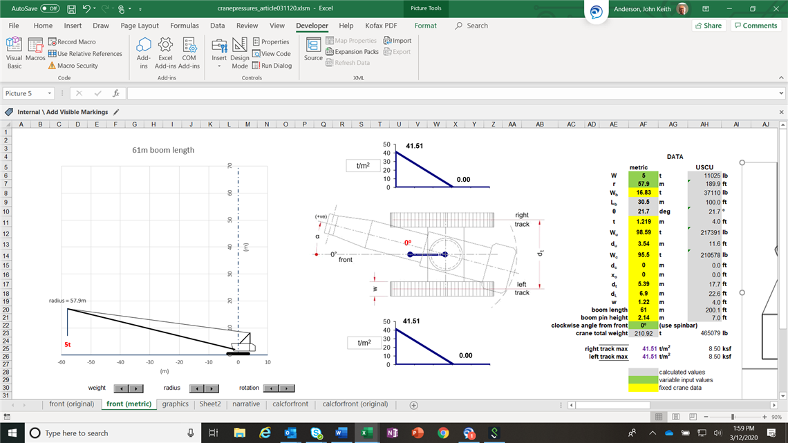
At the maximum radius of 57.9 metres, the crane can lift 5 tonnes. The peak track pressure over the front is about 42 t/m2, which is similar to the previous examples; about 60 % of the track length is loaded.
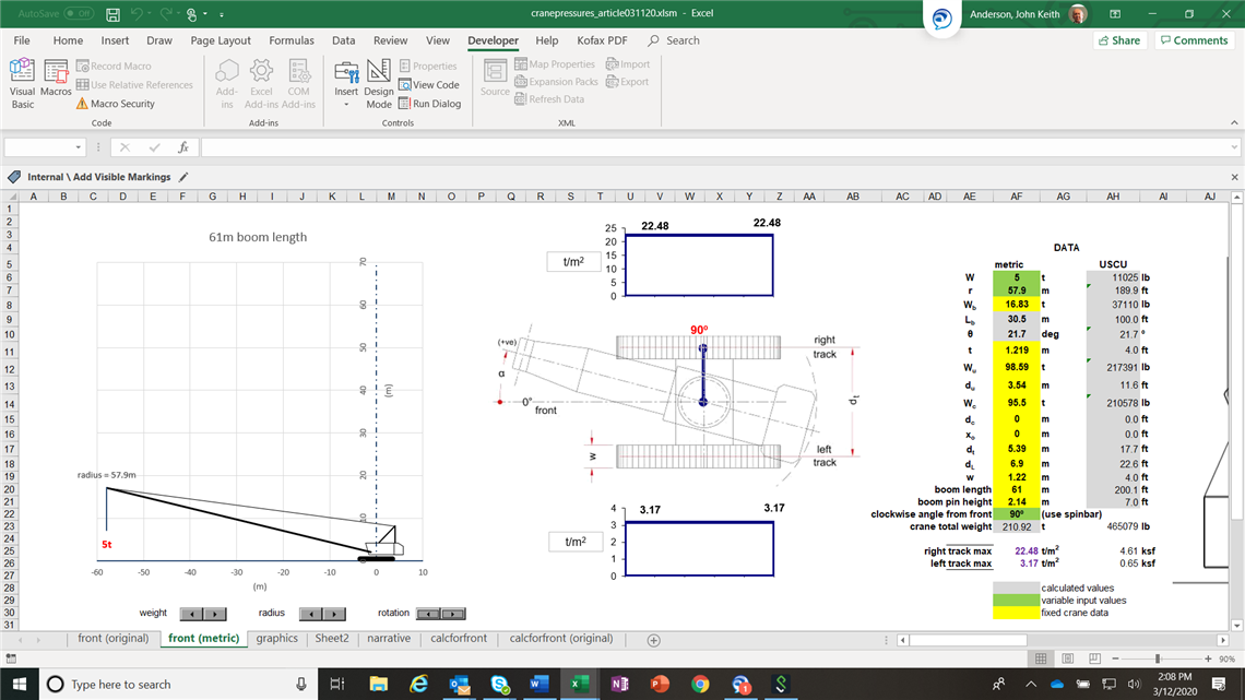
If you were to lift that same load, at the same radius, over the side, the entire bearing length of the track would be evenly loaded and the most highly loaded track would see about 23 t/m2. (The other track only sees a pressure of about 3 t/m2). There is, therefore, a reduction in peak pressure of about 50 %; the orientation of the tracks is worth considering when looking to minimise peak pressures and thereby ground preparation.
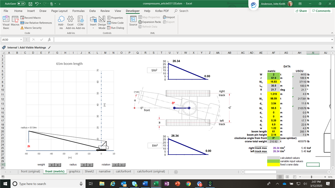
When raising an unloaded boom (I applied 2 tonnes for a hookblock) over the front, the maximum pressure is about 26 t/m2. It should be noted that this crane can self-raise a much longer boom than 200 feet and the pressure would be a lot higher.
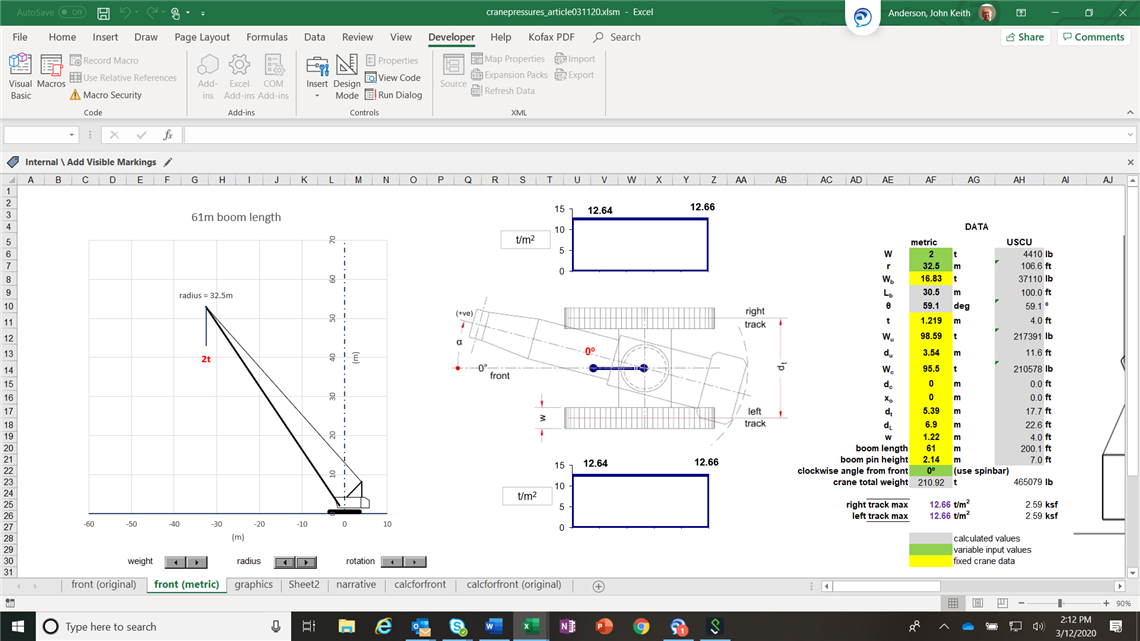
As the boom is further raised, still with 2 tonnes suspended, there is a point at which the crane is perfectly balanced, both tracks being evenly loaded at about 13 t/m2. This would be an optimum (from a pressure perspective) for crawling the crane to relocate it, being only about a third of typical peak pressures when lifting. It is quite likely that a decent site road could cope with this magnitude of undistributed pressure (although that should be verified). Note that in this state of balance, swinging the crane does not change to pressure distribution.
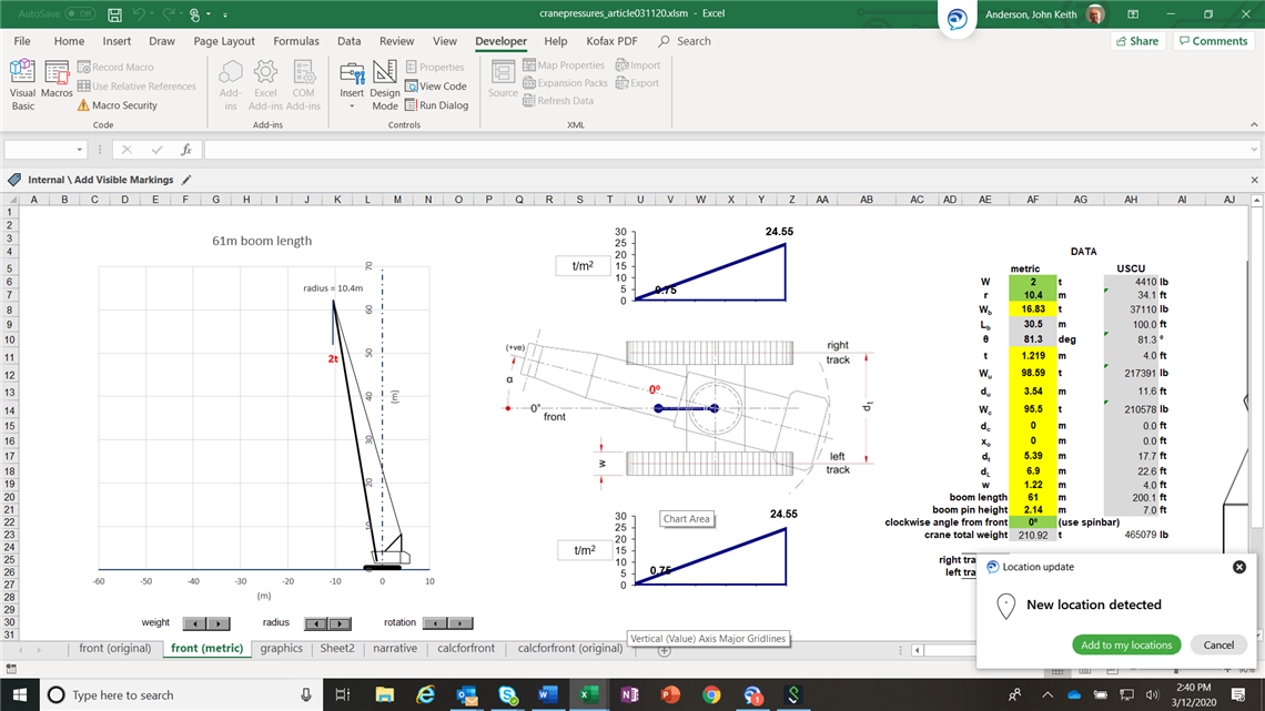
If the crane is boomed back to minimum radius with the boom over the front, in this instance the whole length of the track is engaged, but the crane is back-heavy and the peak pressures are about 25 t/m2. This might not be acceptable on a site road (again verify this).
Take-aways from this exercise include:
- Use the tools out there to best inform yourself when planning a lift.
- Rules of thumb for estimating loads and mat sizing are a poor substitute for good information and should only be used with caution and be very conservative.
- The peak track pressure in our example was similar across the operating range when lifting at maximum chart capacity.
- Less (length) of the track is loaded as radius increases when lifting at chart capacity.
- If the lifting operation can be arranged such that the boom is directly over the side when at long radius, the pressure will be evenly distributed along the tracks and, in our example, the most highly loaded track will be at only half the peak pressure had we been over the front. Note that if the load is initially lifted over the front at close radius before being swung over the side and boomed out, because the load is less than 100 % of the close radius capacity, the peak front track pressures will be less and more of the track will be engaged.
- When raising a crane boom the pressures can initially be very high and, if a crawler crane, it might be better to raise the boom over the side to better spread the load and reduce the pressure.
- When relocating a crawler crane, there will be an optimum mid-range radius at which the crane is well balanced and pressures are minimised, in our example only about one third of typical lifting peak pressures. It is recommended that this radius is identified and used to minimise required ground preparation.
- If the unloaded crawler crane is boomed back to minimum radius during relocation, the crane would be very back heavy; in our example, the peak (backwards) track pressure would be about half the typical maximum peak pressure when lifting at chart capacity. Cranes and configurations may differ but the principle remains.

Keith Anderson is a 40-year veteran of the crane and rigging industry. A UK Chartered Engineer and Fellow of the Institution of Mechanical Engineers he has, since 2001, managed the rigging engineering group at Bechtel. He is the engineering, construction and project management specialist company’s chief rigging engineer.
Anderson is an advocate for professionalism in rigging engineering and lift planning and is active in education through training and speaking to industry groups; he is also a committee member for the ASME P30 Lift Planning Standard.
His well-received book, Rigging Engineering Basics, became a standard text for the rigging industry. A second volume, Rigging Engineering Calculations, was recently published. He was an adviser and a contributor to the ASME accredited Fundamentals of Rigging Engineering course developed by Industrial Training International. Keith is resident in Louisville, Kentucky, USA.
STAY CONNECTED


Receive the information you need when you need it through our world-leading magazines, newsletters and daily briefings.